Ultrasonic Testing

Ultrasonic Non-Destructive Testing is the process of transmitting high-frequency sound waves into a material in order to identify changes in the material’s properties
Ultrasonic methods of NDT use beams of mechanical waves (vibrations) of short wavelength and high-frequency, transmitted from a small probe and detected by the same or other probes. Such mechanical waves can travel large distances in fine-grain metal, in the form of a divergent wave with progressive attenuation.
The technique detects internal, hidden discontinuities that may be deep below the surface. Transducers and coupling wedges are available to generate waves of several types, including longitudinal, shear and surface waves. Applications range from thickness measurements of thin steel plate to internal testing of large turbine rotors.
Best NDT Inspection Technologies Pte Ltd provides a variety of Ultrasonic Testing services including Contact Method, Thickness Bond Testing
- The following discontinuities can be detected using Ultrasonic Testing: Crack, Corrosion on reinforced plastic, Aircraft Structures & Components, Honey comp structures.
- Flaws can be detected in Welds, Castings, Forgings, Plates, Bars, Tubes & Machine components.
Ultrasonic methods of NDT use beams of mechanical waves (vibrations) of short wavelength and high-frequency, transmitted from a small probe and detected by the same or other probes. Such mechanical waves can travel large distances in fine-grain metal, in the form of a divergent wave with progressive attenuation.
The frequency is in the range 0.1 to 20 MHz and the wavelength in the range 1 to 10 mm. The velocity depends on the material and is in the range 1000-6000 m/s.
The technique detects internal, hidden discontinuities that may be deep below the surface. Transducers and coupling wedges are available to generate waves of several types, including longitudinal, shear and surface waves. Applications range from thickness measurements of thin steel plate to internal testing of large turbine rotors.
Most non-porous, resilient materials used for structural purposes (steel, aluminium, titanium, magnesium and ceramics) can be penetrated. Even large cross-sections can be tested successfully for minute discontinuities.
Ultrasonic testing techniques are widely accepted for quality control and materials testing in many industries, including electric power generation, production of steel, aluminium and titanium, in the fabrication of airframes, jet engine manufacture and ship building.
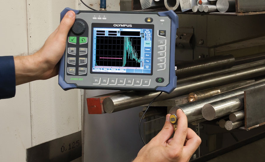
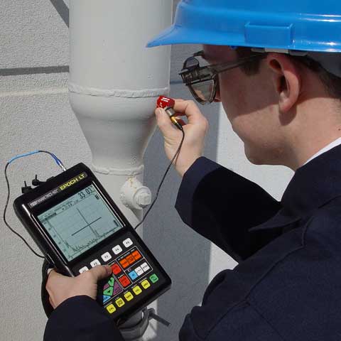
Usually, pulsed beams of ultrasound are used and in the simplest instruments a single probe, hand-held, is placed on the specimen surface. An oscilloscope display with a time-base shows the time that it takes for an ultrasonic pulse to travel to a reflector (a flaw, the back surface, or other free surface) in terms of distance across the oscilloscope screen – the so-called A-scan display. The height of the reflected pulse is related to the flaw size as seen from the transmitter probe. The relationships of flaw size, flaw distance and flaw reflectivity are complex and considerable skill is required to interpret the display.
Complex multiprobe systems are also used with mechanical probe movement and digitisation of the signals, followed by computer storage; methods of computer interpretation are developing rapidly.

There are several forms of mechanical vibration, depending on the direction of particle movement in the wave motion, and so there are several forms of ultrasonic waves, the most widely used in NDT being compressional and transverse (shear) waves.
By suitable design of probe, ultrasonic beams can be introduced into solid material at almost any angle.
Compressional waves will also travel through liquids and a common technique is to immerse the specimen in a large tank and use a stand-off probe with a mechanised movement. With such equipment, alternative methods of displaying the signals are possible and a two-dimensional ultrasonic image can be produced (B-scan and C-scan displays).
Generally, a single probe acts as both transmitter and receiver, so that inspection can be done from one side only of the specimen. Large-grain materials such as austenitic steel welding, copper castings etc produce severe attenuation and scattering and are at present difficult to inspect with ultrasound, but large thicknesses of fine-grain material such as forged steel can be tested without difficulty.
Because the usual indication of a flaw is a pulse on an oscilloscope trace, flaws must be characterised and also sized. New techniques such as time-of-flight diffraction, TOFD, have been developed to assist this technique.
Ultrasonic attenuation and ultrasonic velocity measurements are used to study various material properties.
The use of ultrasonics for sizing flaws

Once flaws have been detected it is often desirable to determine their size. For flaws smaller than the ultrasonic beam width, a pseudo-sizing can be obtained by comparing the flaw signal amplitude with that of a reference reflector (flat-bottomed or side-drilled hole) at the same range. When the flaw size is greater than the ultrasonic beam width, conventional probe movement sizing techniques can often be used to provide an estimate of flaw size. The maximum amplitude technique uses a measure of the probe movement between the maximised signals from flaw extremities to size flaws. The 6 dB and 20 dB drop techniques use the reduction in the signal amplitude from the flaw as the probe passes over the edge of the flaw as an indicator of flaw dimensions. However, the interaction between the ultrasonic beam and flaw, depending as it does on flaw nature and orientation, limits the effectiveness of these techniques, when dealing with complex and mis-orientated flaws.
Techniques which make use of the diffracted signal from the flaw extremities to locate and size flaws are most effective in sizing planar flaws. The time-of-flight diffraction (TOFD) technique uses the ultrasonic transit time between probe(s) and flaw extremities to locate and size flaws. Flaw sizing accuracies of better than ±2 mm can be achieved with optimised techniques (see also Ultrasonic advanced methods).
